Robin House Children’s Hospice
Provision of access incorporating a fully encapsulated UBIX temporary roof system to support the roof repair and replacement project.
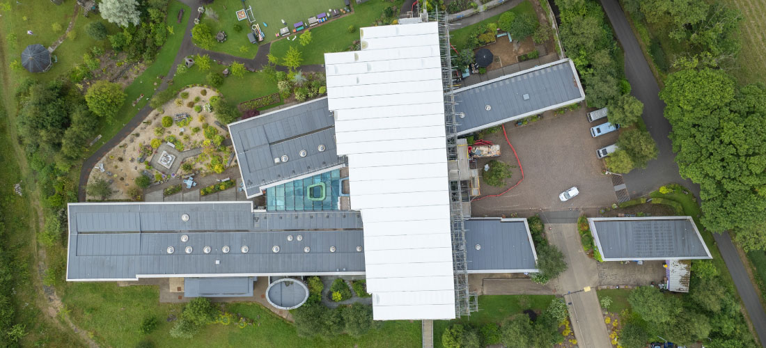
Robin House opened in the autumn of 2004 and is operated by CHAS (Children’s Hospices Across Scotland). The modern building nestled into the surrounding landscape is located within Loch Lomond National Park and was designed by Hoskin Architects, Glasgow, with a “ribbon roof” to replicate the waves of the loch. The shaped roof creates a unique identity for the building while maximising daylight, and the hospice is organised into wings with two glazed internal courtyards housing a den, an art room, and a hydrotherapy pool to provide a “home from home” for families caring for terminally ill children. Buildings on the six-acre site are surrounded by a large accessible landscaped garden space maintained by a dedicated team of volunteers.

Project Summary
We were initially made aware of the sensitive project by DM Hall Chartered Surveyors and informed that the hospice would continue to be fully operational throughout the planned work programme schedule while the scaffold remained erected. So, we consulted with stakeholders from the hospice, DM Hall Chartered Surveyors, and Aim Developments to minimise disruption on-site for residents or visitors by initiating meticulous planning and carefully reviewing every detail.
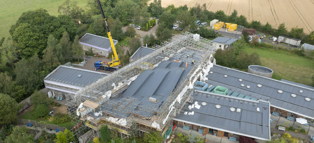
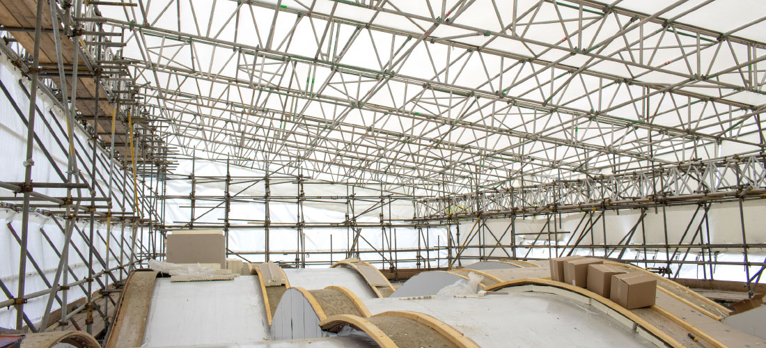
Then, to support primary contractor Aim Developments (a leading specialist with flat roofs) with roof replacement and repairs at Robin House, we installed a fully encapsulated UBIX temporary roof system with edge protection to create a secure weatherproof environment. The UBIX roof system and system sheeting were both utilised to span over the existing building and supported by towers on the East and West elevations.
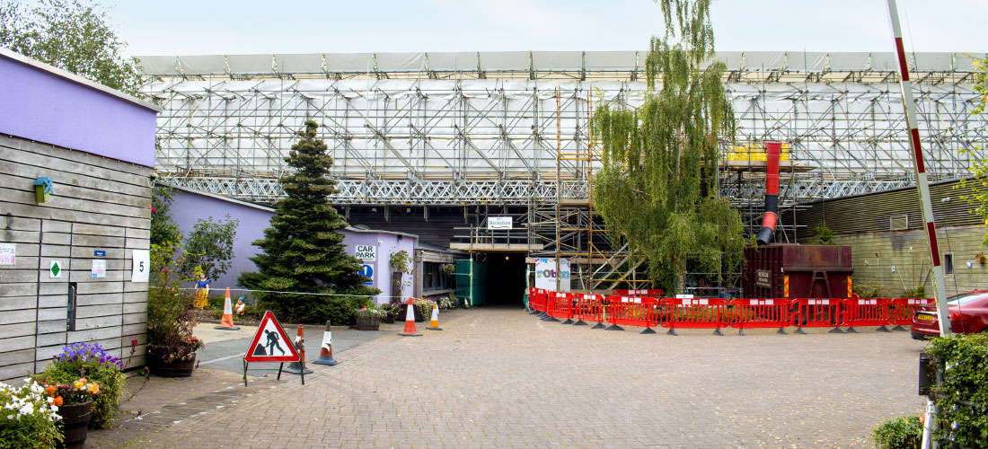
The temporary roof is supported by the surrounding 5-lift high tube and fitting independent scaffold and is fully boarded at roof level to permit easy access. Also, an additional level is boarded below the header beam level to allow for the installation of roof beams. Additionally, the vertical side elevations of the scaffold structure were fitted with fire-retardant sheeting installed from the eaves level up to the roof beam level. We also installed a Kwikstage stair unit at the front entrance to provide tradespeople with safe access to the boarded lift at the roof canopy level.


Value Engineering
Initially, the scaffold was stabilised by tying it to the concrete blocks of the building at a low level using 12mm Apollo screws. However, the ties were light-duty and unable to support the full height of the scaffold. Therefore, the width of the scaffold was increased by implementing buttresses.
Horizontal loads for the scaffold roof were catered for by butting to the side of the canopy, which is a curved steel girder. Butts installed on the underside of the canopy girder catered for potential uplift reactions created by wind acting on the sheeted roof.
Front elevation (West elevation)
Due to restrictive tie locations, the West was chosen as the primary elevation to support the horizontal loads from the roof and consisted of a support bay with buttressing. There were two locations where the support bays couldn’t be built from ground level due to low-level roofs. Therefore, scaffold beams were bridged over the low-level roofs to support the scaffold.
Rear elevation (East elevation)
The rear elevation was complex, as the scaffold could only be ground-bearing at the northeast corner because most of the elevation was positioned above the low-level roof, which meant bearing locations were limited. Scaffold beams were used to bridge over the low-level roofs with two support points to reduce the span of the bridged beams. One bearing point was on a wall head, while at the second point, the scaffold was footed on RMD superslim soldiers that spanned over existing steel girders. The vertical loads applied to these bearing points were approved by a client-appointed structural engineer.
North elevation
The North elevation was ground-bearing, with only a short beam span required over an existing pedestrian bridge. So the elevation could be tied to the concrete blocks of the permanent structure using 12mm Apollo screws.
South elevation
The South elevation of the building has a long canopy, so we utilised a birdcage arrangement that also provides greater width and stability. Our in-house design and engineering team had to consider the need for access/egress to existing doors for moving patient beds.

